

VaxStation 2000
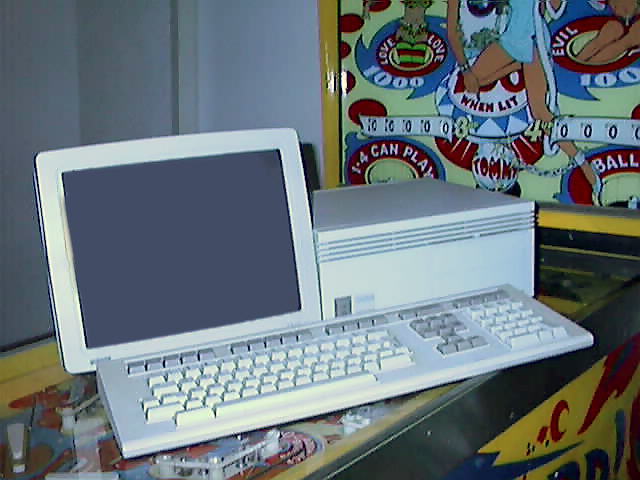
The VS2000 is a small and somewhat slow "VAX in a lunch box". It is great for the beginner to experiment with, not as noisy and not as big as other VAX systems. It will run VMS, Ultrix and NetBSD, and it is possible to hook a graphical monitor up to it.
VAXstation/microVAX jumper
The MicroVAX 2000 and the VAXstation 2000 really are the same machine. You can set a jumper on the system board to tell the system how to behave.
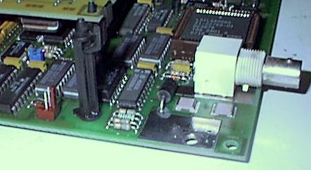
On the KA410 motherboard about two inches or so directly behind the thin ethernet BNC connector:
- VAXstation 2000: jumper on pins closer to thin ethernet BNC
- MicroVAX 2000: jumper on pins farther away from the thin ethernet BNC
A blue jumper was used for the picture, so you could see it more easily here, but the original jumper is black.
There are four serial ports on the cpu board. On the MicroVAX 2000, these become the console and three terminal ports. On the VAXstation 2000, these become the printer port, keyboard, mouse and modem interface.
Both machines have a mono (1024x864x1) frame buffer on the CPU board. You enable or disable it (read: change it from a MicroVAX 2000 to a VAXstation 2000 and back) by inserting or removing the jumper.
Also this jumper toggles a flag in the configuration register (the "server flag") which is checked by some VAX/VMS software in order to decide which and how many licenses you need. This flag is used by NetBSD only to decide which string to diplay, "MicroVAX 2000" or "VAXstation 2000"
Console cable
If the graphics board has been disabled with the jumper, the console is switched to the printer port. However, to get the console to appear on the printer port, setting the jumper is not required. It is possible to force a VS2000 to use a serial console without fiddling with the jumper on the motherboard.
The 2000 has four serial ports: the 25-pin comm port, the 9-pin printer port, and two ports on the 15-pin video port for the mouse and keyboard. Normally, to connect a printer to the 9-pin printer port you use a BCC05 cable. If you use a BCC08 cable, the 2000 will use the 9-pin port as its console. The BCC08 shorts pins 8 and 9 of the 9-pin port together to signal it should be used as a console. The other interesting pins on the 9-pin port are:
	1 - Shield GND
	2 - Transmitted data
	3 - Received data
	7 - Signal GND
This is the console cable:
   VAX 9 pin console          PC 9 pin serial        PC 25 pin serial
   1 - Shield GND             2 - Received data      1 - Shield ground
   2 - Transmitted data       3 - Transmitted data   2 - Transmitted data
   3 - Received data          5 - Signal GND         3 - Received data
   7 - Signal GND             1 - DCD                7 - Signal GND
   8 - sense console 1        4 - DTR                8 - DCD
   9 - sense console 2        6 - DSR               20 - DTR
                              7 - RTS                6 - DSR
                              8 - CTS                4 - RTS
                                                     5 - CTS
The cable

VAX         PC9 PC25
2 ---------  2   3

3 ---------  3   2

7 ---------  5   7

8 -+     +-  1   8
   |     |
9 -+     +-  4  20
         |
         +-  6   6

         +-  7   4
         |
         +-  8   5
Do not forget to short pins 8 and 9 on the VAX side, for some VS2000s this is required to make the console work, regardless of the setting of the jumper.
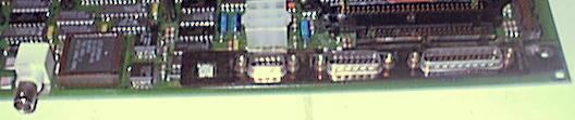
Connectors on the system board
Printer/console port (J3)
1 - ground      2 - xmit_data   3 - rcv_data
4 - no conn     5 - +12VDC      6 - no conn
7 - ground      8 - ground      9 - fer_ena (jumper to pin 8 for console)

Video Connector (J5)
1 - vid_red     2 - color_ret   3 - mono_ret
4 - +5VDC       5 - mouse_rcv   6 - kbd_grnd
7 - ground      8 - +12VDC      9 - vid_mono
10 - vid_green  11 - vid_blue   12 - -12VDC
13 - mouse_xmit 14 - kbd_rcv    15 - kbd_xmit

The interesting pins in the video connector from a serial port perspective
are:

	6 - GND for keyboard
	14- Received data from keyboard
	15 - Transmitted data to keyboard

	7 - GND for mouse
	5 - Received data from mouse
	13 - Transmitted data to mouse

There is a plastic box about the size of a cigarette pack that plugs
into the db9 printer port and db15 keyboard/mouse/video cable
connector and screws into place outside the main chassis.  It takes
over that db9 and db15 and gives you three DECconnect (MMJ) connectors
for terminal ports for the MicroVAX 2000 configuration.
It is possible (if you have the connectors lying around) to build cables to
break out the serial ports without needing the DEC box. Just use the pinouts
described above.
Comm Connector (J10) - RS232 with partial modem control
This is a standard 25-pin serial port.
Tape Port Connector (J13) - single ended SCSI
This connector has the standard 50-pin SCSI-1 pinout.
RD/RX Cable Pinout (J7)
1,3,5,7,9,11,13,15,17,19,21,23,25,27,31,34,37,40,43,46,48,51,54,57,60 - ground
 2 - lospeed
 4 - rxindex
 6 - rxsel0
10 - moron
12 - rxdir
14 - rxstep
16 - rxwd
18 - rxwrgt
20 - rxtk00
22 - wrtprot
24 - rxrdata
26 - rxhsel0
28 - rxrdy
29 - rdhsel3
30 - rdhsel2
32 - rdwrgt
33 - skcompl
35 - rdtk00
36 - wrtfault
38 - rdhsel0
39 - rdhsel1
41 - rdindex
42 - rdrdy
44 - rdstep
45 - rdsel0
47 - rdsel1
49 - rddir
50 - dselack
55 - rd0_wdath
56 - rd0_wdatl
58 - rd0_rdath
59 - rd0_rdatl
8,52,53 - no conn

Expansion Disk Data Cable (J9)
2,4,6,8,11,12,15,16,19 - ground
3,5,9,10,20 - no conn
 1 - dselack
 7 - +5Vdc
13 - rd1_wdath
14 - rd1_wdatl
17 - rd1_rdath
18 - rd1_rdatl
MFM Hard disk connectors
The other end of the cable must have this pinout:
Hard disk 34 pin connector
 4 - head select 2
 6 - write gate
 8 - seek complete
10 - track 0
12 - write fault
14 - head select 0
18 - head select 1
20 - index
22 - ready
24 - step
26 - drive select 1
28 - drive select 2
30 - drive select 3
32 - drive select 4
34 - direction in
1-33 ground (odd numbers)
2,16,30,32 reserved

Hard disk 20 pin connector
 1 - drive selected
 5 - key
13 - +mfm write data
14 - -mfm write data
17 - +mfm read data
18 - -mfm read data
2,4,6,8,10,11,12,15,16,19,20 ground
3,5,7,9 reserved
all other pins unused.

Floppy drive 24 pin connector
 2 - mode select
 4 - in use
 6 - drive select 3
 8 - index
10 - drive select 0
12 - drive select 1
14 - drive select 2
16 - motor on
18 - direction select
20 - step
22 - write data
24 - write gate
26 - track 0
28 - write protect
30 - read data
32 - side 1 select
34 - ready/disk change/open
1-33 ground (odd numbered pins)
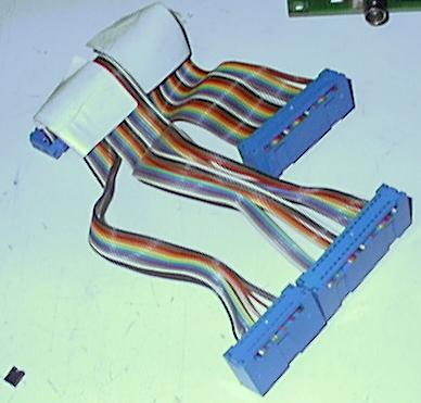
Building a replacement cable
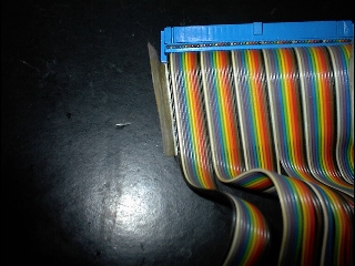
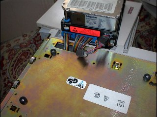
With the pin numbering information above you should be able to build a new cable. Problem is that there are less wires going to the disk connectors than there are pins in the connectors, so while putting the cable in the connector you are going to have to skip pins, as you can see in the pictures.
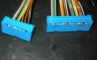
19                     2   34                                   2
  XOOOOXOOOXXXOXXOXXOO       OOOOOXXXXXOOOX000XXXOOOX000XOOOXOX
20                     1   33                                   1
This is where the wires should be on the hard disk connectors.
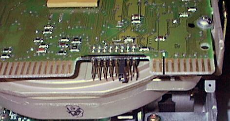
This is where the jumper on the RD32 hard disk should be, jumpered as the third of four drives.
The floppy drive should be jumpered as ID0, the first drive.
Formatting the hard disk
It is very useful to have a VS2000 around, if only to format hard disks with. For a MFM hard disk to work in a MicroVAX it must have a very peculiar format written to it. The VS2000 and the Q-bus RQDX3 controller for the MicroVAX II et al require this format to be present. The VS2000 is the only DEC device that can write this format without expensive hard to get software: the formatter is present in the VS2000 ROM under the TEST 70 command. If the formatting of a disk you are using on a RQDX controller is damaged, you can format the disk in a VS2000 and hook it back up to the RQDX controller, the disk will work like new. Click on this link to read how to format a disk in the VS2000.
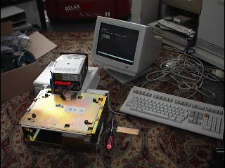
This is how I format hard disks with my VS2000. I have brought the existing cables to the outside of the box via the opening that is there to connect the expansion unit to the computer. Just remove the plate and you can pull the cables through it. Very easy!
Thanks
Thanks to Dave McGuire (mcguire@digex.net), Rick (rick@snowhite.cis.uoguelph.ca), Roger Ivie (ivie@cc.usu.edu), Bertram Bach (), whose posts to the NetBSD/VAX mailing list provided much of the above info.